B10 Scan Tool
This is a very simple scan tool to read some parameters in realtime from the
ECU on 1990-1994 North American Subaru Legacy models using x86-based
computers.
Connecting to the car
Diagnosis connector
|
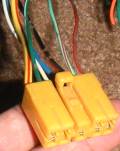 Under the driver side dash there is a yellow 9-pin diagnosis connector
intended to interface with the Subaru Select Monitor. It may be easier to
locate and access this connector if the trim panel below the steering
column (held in place with several Phillips-head screws) is first removed.
Through this connector is the preferred way to use this scan tool.
Under the driver side dash there is a yellow 9-pin diagnosis connector
intended to interface with the Subaru Select Monitor. It may be easier to
locate and access this connector if the trim panel below the steering
column (held in place with several Phillips-head screws) is first removed.
Through this connector is the preferred way to use this scan tool.
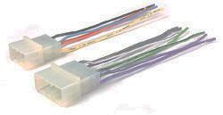 This
connector happens to have the exact same shape as the speaker connector
for the radio, so the simplest way to connect to it would be to start with
an aftermarket stereo harness adapter such as Metra part number 70-1780 or
Scosche part number SU02B. These adapters should be available at any store
that sells car audio equipment. This
connector happens to have the exact same shape as the speaker connector
for the radio, so the simplest way to connect to it would be to start with
an aftermarket stereo harness adapter such as Metra part number 70-1780 or
Scosche part number SU02B. These adapters should be available at any store
that sells car audio equipment.
|
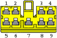
The pins used by this scan tool are:
|
| Pin
| Wire Color (Main/Stripe)
| Description
|
| 2
| Green/White
|
| Transmit
|
| 3
| Light Green/Red
|
| Receive
|
| 9
| Black/Red
|
| Ground |
Of course, since you're only connecting to three wires (and in principle you
can tap the ground reference from any other ground on the vehicle), you may
simply choose to splice into the wires directly or use some other means of
connecting to the pins.
ECU connector
Though it is not recommended, you can also tap these wires by the ECU itself.
This may be required if you've swapped an EJ22 from a first-generation Legacy
into another car but did not use the complete wiring harness, or if your
diagnosis connector has been damaged.
The signals needed by this scan tool can be found on the 16-pin connector of
the ECU harness. This diagram is of the connector on the harness, not on the ECU
itself.

|
| Pin
| Wire Color (Main/Stripe)
| Description
|
| 8
| Green/White
|
| Transmit
|
| 7
| Light Green/Red
|
| Receive |
While it is possible to tap ground from one of the sensor shields or returns
on this connector, it is better to simply use another ground more easily
accessible.
Connecting to the computer
Warning
Whenever you connect a new device, particularly a homemade one, to your
computer, you are taking a risk. If you wire everything precisely as I describe
here, chances of causing damage to your computer or ECU are minimal but not
nonexistant. Be careful, and double-check everything!
Parallel port
This scan tool is designed to communicate with the ECU's diagnosis port
through the parallel port of an IBM-style computer (most likely a laptop of
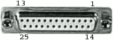
course). Also often called the printer port, it is physically a female DB-25
connector. The pins used by this scan tool are:
|
| Pin
| Description
|
| 1
| Strobe
|
| 13
| Select
|
| 25
| Ground |
|
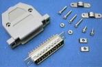 Mating connectors of various types are easily found at a good electronic
parts store or Radio Shack. They generally either use crimp-on pins or
have solder cups for each pin. Usually, if you look closely you can see
pin numbers stamped into the plastic, which can help you make sure you're
connecting to the correct pin. It makes good sense to get a hood (plastic
or otherwise) to give you something to grip when you need to unplug the
connector.
Mating connectors of various types are easily found at a good electronic
parts store or Radio Shack. They generally either use crimp-on pins or
have solder cups for each pin. Usually, if you look closely you can see
pin numbers stamped into the plastic, which can help you make sure you're
connecting to the correct pin. It makes good sense to get a hood (plastic
or otherwise) to give you something to grip when you need to unplug the
connector.
It would also be fairly easy to cannibalize a printer cable or
something similar. Every parallel printer cable will have wires attached
to each of these pins. Note, however, that a serial (RS-232) or SCSI cable
with DB-25 connectors may not. |
The scan tool simply requires the diagnosis port's "transmit" line to be
connected to the parallel port's "select" line, the diagnosis port's "receive"
line to be connected to the parallel port's "strobe" line, and for the grounds
to be connected:
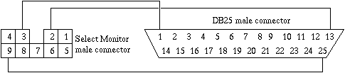
If you're tapping these lines right at the ECU, you need to connect the same
ECU signals to the same parallel port pins.
Serial port
The scan tool also has experimental support for communication using RS232
serial ports. The voltage levels aren't right, and a few extra components are
required, so this method is not recommended if there is any other choice. It may
work for you though.
On most computers, the serial port is a male DB-9 connector. On certain older
computers it may be a male DB-25 connector, however. The pins you would use are:
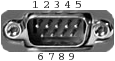
Male DB-9 port
|
| DB-9 Pin
| Description
| DB-25 Pin
|
| 1
| Data carrier detect
| 8
|
| 3
| Transmit
| 2
|
| 4
| Data terminal ready
| 20
|
| 5
| Ground
| 7
|
| 7
| Request to send
| 4 |
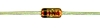
To deal with the differing voltage levels, four components are needed. These
should be easily found at any electronic parts store:
Two 10K resistors
(e.g. Radio Shack part number 271-1335)
| 
|
One 1N4733A Zener diode (or other Zener close to 5V)
(e.g.
Radio Shack part number 276-565)
| 
|
One 2N3904 transistor (or other general-purpose NPN transistor)
(e.g. Radio Shack part number 276-2016)
| 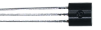 |
The connections are fairly simple, but it is important that you get the
polarity of the diode right (make sure the end with the stripe is pointed the
correct way) and that you get each pin of the transistor right (the pins are
called the emitter, the base, and the collector; refer to the documentation for
the particular transistor you use).
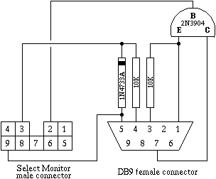
Again, it makes sense to put a hood on the DB9 connector. In fact, the simple
circuitry needed can fit inside the hood.
Binary downloads
The scan tool program is available here in two binary forms. If you just want
to use the scan tool, download one of these. It is licensed under the terms of
version 2 of the GNU General Public License, whose full text is available here:
gpl.txt [about 18
kB]
Raw binary file
b10scan.com
[about 8kB]
This raw binary is bootable. It can be written directly to a diskette or hard
disk and it will load itself into memory and run without any operating system.
Though I have not tested this, I believe it could also be written to a USB flash
drive to be used on a computer that can boot from such devices.
It can also be run under DOS. If your laptop already runs DOS (Windows
95/98/Me in command-prompt-only mode counts), just download the program itself
and run it. It will not, however, run correctly under any kind of multitasking
operating system because timing is very important.
Otherwise, to make a bootable floppy disk, use a tool like Rawrite
(search for Jeremy Davis' writeup for information on Rawrite)
to write it to a disk as a disk image. It is much
smaller than any floppy disk but it will work correctly as only the beginning
portion matters. On UNIX-type systems, you can use the dd command to
copy the contents of the file to a diskette block device.
Bootable CD image
b10scan.iso
[about 1.5MB]
Or, if your laptop has no floppy drive but can boot from a CD-ROM, you could
burn this bootable CD-ROM image to a disc and boot from it. This is just a CD
version of a bootable floppy made as described above.
Running it
When the program is started, it will first shut off the system's drives if
APM is present (this reduces power consumption and also reduces the risk of
vibration in the car damaging the hard disk), and then it will display a quick
info screen. Press a key and it will show a list of parallel and serial ports
found on the system. Use the up and down arrow keys to select the one your cable
is attached to, and press enter.
The scan tool will then use that port to attempt to determine the ROM ID of
the ECU it is connected to. If it succeeds and recognizes the ID, you may
continue on to read parameter values by hitting the space bar. The following
parameters may be viewed in realtime:
- Continuous parameters:
- ROM ID
- System voltage
- Vehicle speed
- Engine speed
- Coolant temperature
- Ignition timing
- Airflow signal
- Load
- Throttle position signal
- Zeroed throttle position (only on 90-91 manual and 91-94 turbo models)
- Injector pulse width (poor granularity on 90-91 models)
- IAC valve duty cycle
- Oxygen sensor signal
- Fuel trim
- Timing correction
- Boost control duty cycle
- Barometric pressure (except on 93-94 non-turbo models)
- Boost/vacuum (only on turbo models)
- Binary parameters:
- Ignition switch
- Automatic transmission mode
- Test mode
- Read memory mode
- Neutral switch
- Park switch
- California mode
- Idle switch
- Air conditioning switch
- Air conditioning relay active
- Radiator fan relay active
- Fuel pump relay active
- Canister purge valve active
- Pinging detected
- Pressure exchange (only on turbo models)
I do not know the precise system requirements of this program. It was written
without the use of any OS system calls or 32-bit instructions. It does require a
true IBM-compatible parallel port, of course. The processor must be at least an
80286 and be fast enough to do all the necessary processing without losing
timing; I have no good guess as to how fast is fast enough. The video adapter
must be CGA compatible. Though the program itself is tiny, the way the
bootloader is written requires the machine to have something like 80 kilobytes
of RAM.
Source code
b10scan-0.06.tar.gz
[about 20kB]
This scan tool is free software and is licensed under the terms of version 2
of the GNU General Public License, a copy of which is included in the source
archive.
The source code available here is meant to be assembled with nasm.
mkisofs is used for building the bootable CD image. The included
makefile should work with most any make implementation.
Contact info
I highly recommend that any 1st-generation Legacy owner visit Legacy Central
BBS:
https://bbs.legacycentral.org/
Begin by browsing the forums (especially reading any "sticky" threads), and
then by searching through existing posts. A great wealth of information for our
cars is present. My username on Legacy Central is vrg3.
My email address is v graphics.cornell.edu.
Version history
- Version 0.06 (27 March 2006)
- b10scan-0.06.tar.gz
Changed
name to "B10 Scan Tool."
Added port selection menu.
Added support for
serial port connections.
Added home page URL and serial port interface to
info screen.
Reversed 92-94 NA transmission ID reporting, which apparently
was backwards before.
Added feature to clear display if current sample is
more than a second old.
Added zeroed throttle position for 90-91 5MT and
91-94 turbo ECUs.
Fixed bug that caused APM detection to fail on some
computers.
Ported from TASM to NASM.
Added a simple bootstrap loader to
make scan tool self-booting and eliminate dependency on DOS.
Released under
GPL.
- Version 0.05 (11 May 2004)
- bcbfscan_0.05.zip
Added
feature to spin down hard drives upon program startup.
Corrected small
errors in water temperature readings for 90-91 5MT and 91-94 turbo
ECUs.
Changed manifold pressure units from torr to psi (for boost) and inHg
(for vacuum).
- Version 0.04 (30 April 2004)
- bcbfscan_0.04.zip
Fixed
bug where 92-94 turbo injector pulse widths were displayed as being 16 times
longer than they actually were.
- Version 0.03 (30 April 2004)
- bcbfscan_0.03.zip
Fixed
bug where ROM ID would sometimes not appear initially.
- Version 0.02 (30 April 2004)
- bcbfscan_0.02.zip
Updated
to add digital parameters and support non-turbo models as well as 91 turbo
models. Changed name to "BC/BF Scan Tool."
- Version 0.01 (25 April 2004)
- 22t_scan_0.01.zip
Original
version. Only supported 92-94 turbo models. Named "EJ22T Scan Tool."
Disclaimer
I make no guarantee of any kind that this information is accurate or that
this software will serve any purpose.